System Management Software
Universal Serial Bus
Jeff Chen
The Next Generation of
Peripheral Connections for PC Systems
What Is USB?
Universal Serial Bus (USB) is an emerging industry standard for the connection of
external devices to a PC. The new USB standard includes a universal connector, high speed
access, more robust Plug And Play capability, and the ability to connect devices to hubs
in a tiered-star physical topology.
This paper presents background information about the development of the USB standard
and the general framework of this emerging technology.
Why USB?
Port Expansion
For years, the x86 PC universe has struggled without a good interface for the addition
of external devices. The lack of a bidirectional, low-cost, low-to-mid speed peripheral
bus has restrained the creative proliferation of peripherals such as telephone/fax/modem
adapters, answering machines, scanners, PDAs, keyboards, mice, etc.

Extending Plug and Play
Following the successful introduction of the Plug and Play standard, which is mainly
applied inside the PC system box, a group of PC industry participants led by Intel and
Microsoft tackled the issue of external I/O devices. The resulting 12-Mb/s USB is designed
to provide a single interface that can make outside-the-box plug and play of serial
devices a reality.
Cleaning Up PC I/O
Once USB is implemented, the back of the average PC will change greatly. The backs of
most PCs now may have a keyboard connector, a mouse port, a parallel port, a joystick
port, two audio ports, and two serial ports. This proliferation of ports will likely
disappear, replaced by just two or three USB ports.
The USB standard will greatly enrich mobile computing. Just one or two standard USB
ports can replace the current jumble of as many I/O ports as possible crammed into very
limited space, saving both precious space and costly design effort. Mobile computer users
will have easy, simultaneous access to a wide range of peripheral devices previously
unavailable except through complex reconfiguration or separate docking apparatus.
Connecting the PC to the Telephone
Telephony applications of PC computing are not yet widely accepted, because PCs are
handicapped by conventional serial ports with a bandwidth too narrow for modern
telecommunication applications. In addition, current PC serial ports are limited to
connecting one device at a time, and they don't provide power.
The USB can not only provide bus power to all devices attached to the bus, but it also
supports enough bandwidth for modern telecommunication devices, such as the ISDN modem or
PBX.
Covering Multimedia Applications
The sophisticated design of the USB can accommodate the wide bandwidth desired when
reading an MPEG-2 compressed video data stream from a CD-ROM drive. Analog devices, such
as microphones and speakers, can also be supported if the manufacturers of such
peripherals would install digital-to-analog or analog-to-digital converters in their
devices.
Hot Plugging
Any PC standard proposing ease of use for end users must support "hot
plugging" (i.e., insertion or removal of a device while full power is applied). The
USB will support hot plugging of peripheral devices in much the same way that PC card
sockets in notebook PCs support hot plugging of PC cards. The USB-aware operating system
and BIOS/device driver will establish communication pipes between the host and the device
to provide Plug and Play capability for those devices. This feature of hot plugging USB
devices eliminates the need to restart or reboot the system to use a newly inserted device
or remove a device.
Ease of Use and Low Cost
For the USB to fulfill its promise as the next pervasive industry standard, simplicity
and low cost are very important factors to be considered.
For the user, simplicity means no longer needing to install or configure add-in cards.
Instead, the bus must detect devices whenever they are added or removed, even when the
power is on, without requiring the user to reboot the system.
Low cost is very important to encourage the widespread adoption of the USB standard by
peripheral vendors. The USB is designed to add little if any to the cost of conventional
port circuits. The USB takes advantage of the host PC's ample processing power to take
care of the devices attached to the bus, instead of using a microcontroller built intO
each device to manage the port circuits. As USB becomes a widely accepted standard, a USB
host controller will become part of the core logic chipset on the main system board.
The other feature that keeps down the cost of a USB system is the moderate data rate of
the bus, which turns out to be an important factor in the cost of the cable.
Other Serial Buses
There are some competitors to USB, such as Philips' Access.bus and Apple's GeoPort, but
none of them covers the broad range of applications or has the PC industry backing to
match USB. As shown below, the USB performance range falls between Access Bus and
Firewire.
Table 1. Comparison of Serial Bus Standards
USB Framework
USB Topology
The USB uses a tiered-star physical topology, with one host supporting up to 63
devices. The USB requires that only one peripheral device, for example the keyboard, must
plug directly into a universal connector at the back of the PC. Other devices on the bus
may simply daisy chain together (that is, one connects to the other in a chained
arrangement) or connect in a star topology to a port expansion hub. The maximum distance
from one device to another, whether daisy-chained or plugged into a hub, is 5 meters.
Devices that daisy-chain have one logical port consisting of two physical connectors
for connecting to the upstream and downstream devices on the daisy-chain. The last device
on the daisy-chain must be terminated.
Hub devices have one connector for input from the host or upstream USB device and
multiple connectors for downstream star connectivity.
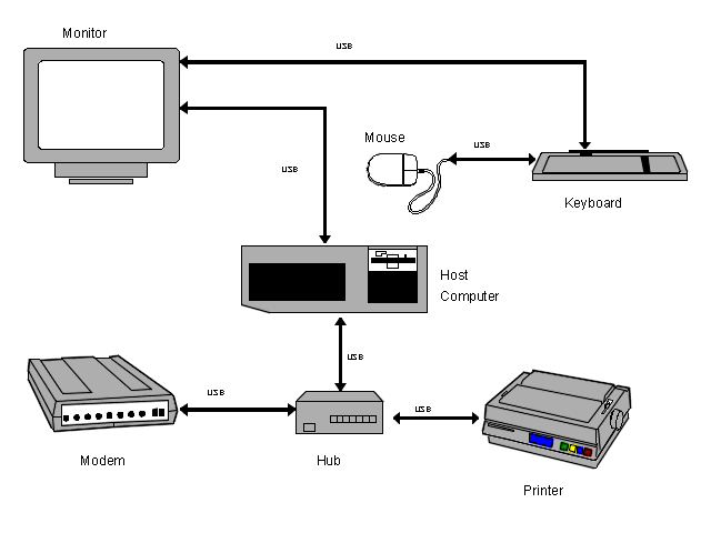
Figure 1 shows typical USB peripheral connections to a microcomputer system:

Figure 1. Example USB System
The system shown in Figure 1 is composed of a host computer with two root USB ports and
five USB peripheral devices:
As shown in Figure 1, the mouse connects to the keyboard, which then plugs into the
monitor. The printer and modem connect to the hub; the hub and monitor plug into the USB
host computer.
In this system, all USB devices communicate with the host computer through the USB
connections from the monitor and hub to the two root ports on the host.

The Transfer Queue
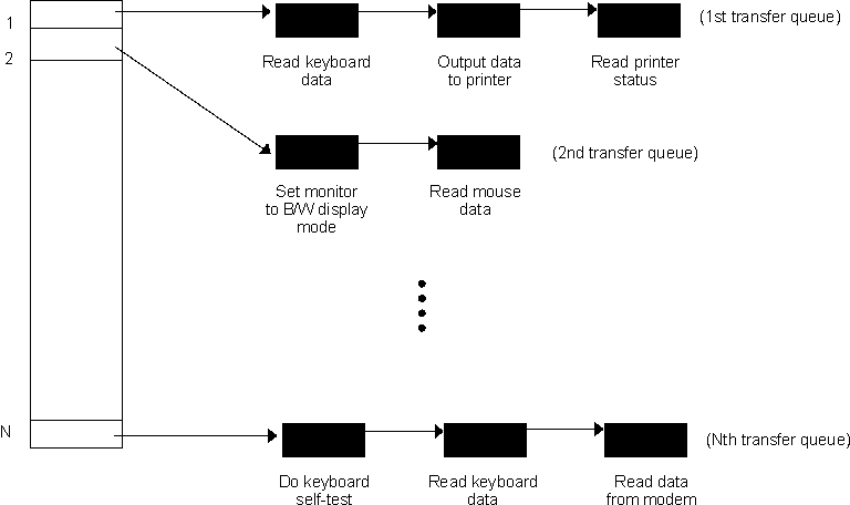
The inter-operations among USB devices are governed by the USB host controller through
a bus transfer mechanism called transfer queuing. The transfer queue plays an important
role in a USB system. System software builds the transfer queue. Figure 2 illustrates the
operations of a transfer queue.

Figure 2. Transfer Queue Operations
Before the host controller can initiate a transaction for a USB device, the USB driver
places a bus transaction request in the transfer queue. The host USB controller inspects
the transfer queue and responds to the bus transaction requests it finds there.
Communications between the USB host controller and all the USB devices connected to the
bus are carried out sequentially, in FIFO order as entered in the transfer queue.
A bus transaction request consists of a transfer request and information useful
to the host controller.
 | The transfer request may be for sending a USB command to a USB device, or reading
data from or writing data to a USB device. |
 | The useful information includes device address, location of the data buffer, type
of transfer (isochronous, interrupt, bulk or control), maximum number of data bytes in
this transmission, and so on. |

Bus Transactions
When the host controller executes a bus transaction as specified in the transfer queue,
it constructs a data packet that contains the contents requested in the transfer request.
The controller sends the data packet to the USB. Along the USB, all devices receive the
same packet, but only the targeted device responds. When the transaction for a USB device
is complete, the next bus transaction in the transfer queue will be executed in the same
manner.
The host controller must execute the bus transaction within one millisecond. If the
data in a transaction requires longer transmission time, an extra USB transaction request
is placed in the transfer queue for another time frame.
A USB transaction can fall into one of the following two categories:
- Device control/status transfer
- Device data transfer
The bus transactions for device control/status are used by the host controller to
configure USB devices. The bus transaction for data transfer involves data flow between
host controller and a USB device.
For example, the command that configures a USB speaker to operate in stereo mode is
output to the speaker in a device control transfer, while the audio data sent to the
speaker is via data transfer.
The direction of data flow may be from host to device, such as a block of data sent
from host to a printer for printing, or from device to host, such as data indicating which
key is pressed, reported from a keyboard to host. However, the direction of a device
control/status transfer is always from host controller to device.

Software Architectural Overview
Inter-Layer Relationships
The USB Software Architectural model can be simply viewed as a set of communication
services between a host and attached USB devices. The USB Host can be logically divided
into a USB host interface, the system software portion (USB system software and host
system software), and the client software (device software) portion. USB devices are
logically partitioned into a USB peripheral interface portion, a USB logical device
portion (a collection of endpoints) and a functional portion.
USB clients (including drivers and applications) are responsible for sending and
receiving data through the USB driver (USBD) layer of a USB-aware operating system (such
as Windows 95). The USBD layer must interface to different existing USB functions,
including keyboard, scanner, printer, mouse, etc.
The USBD layer interfaces to a hardware-dependent layer called the Host Controller
Interface (HCI). This layer of software is responsible for communicating between the USBD
and the hardware chips. There are two major implementations of the Host Controller
Interface: Universal HCI and Open HCI.
The main difference between Universal HCI and Open HCI is that Universal HCI requires a
keyboard controller in the system, while Open HCI furnishes a controller emulation in the
USB system software.
Legacy Mode Support
Legacy mode is an industry term indicating backward compatibility with ISA AT BIOS and
hardware functions. USB system software is too large and complicated to include in a PC
BIOS EPROM. However, because access to BIOS SETUP, optional ROM scanning, and other user
control options during POST is still strongly desired for some USB input devices, support
for certain Legacy functions is implemented in the PC BIOS, rather than in the USB driver.
Legacy mode support in the USB BIOS is mainly designed to be available to USB devices at
POST time and after the USB-aware operating system takes control of the system.
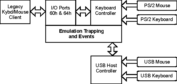
A USB system with a keyboard controller (KBC). Write accesses to the KBC cause
emulation trapping. This trapping allows KBC commands to be propagated to USB peripherals
when appropriate.
Emulation events are generated when the USB host controller has completed a
transaction. Part of the service of emulation events is to insert data into the KBC. The
KBC then generates the appropriate interrupt and makes the data available on the I/O bus.
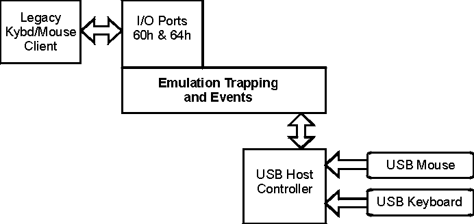
A system with a keyboard controller emulator. As in the previous model, write accesses to
the KBC emulator cause emulation trapping. Emulation events function similarly, except
that there are no PS/2 peripherals and no KBC. Emulation software and minimal emulation
hardware are responsible for generating the appropriate interrupt request and presenting
the data to the CPU.
Sources
Universal Serial Bus Specification, Version 1.0. 19 January 1996. Compaq
Computer Corporation, Digital Equipment Corporation, IBM PC Company, Intel Corporation,
Microsoft Corporation, NEC, Northern Telecom.
Universal Serial Bus PC Legacy Compatibility Specification, Version
0.8a. 30 April, 1996. USB Implementers Forum.


